Bay Weld Boats
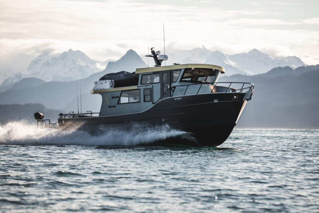
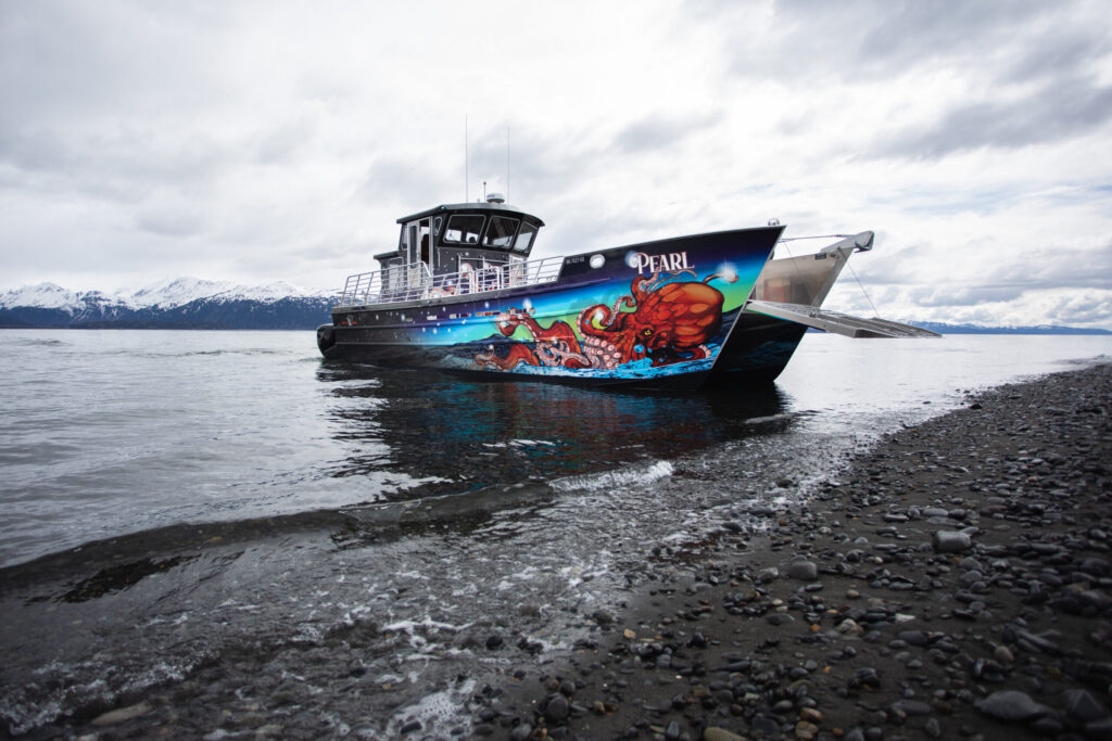
At Bay Weld I worked across the many processes that bring a boat to life: from concept generation and client proposals, to modeling Subchapter T hulls, drawing as-built electrical systems, and the documentation it takes to get COIs approved and boats on the water.
GA drawings
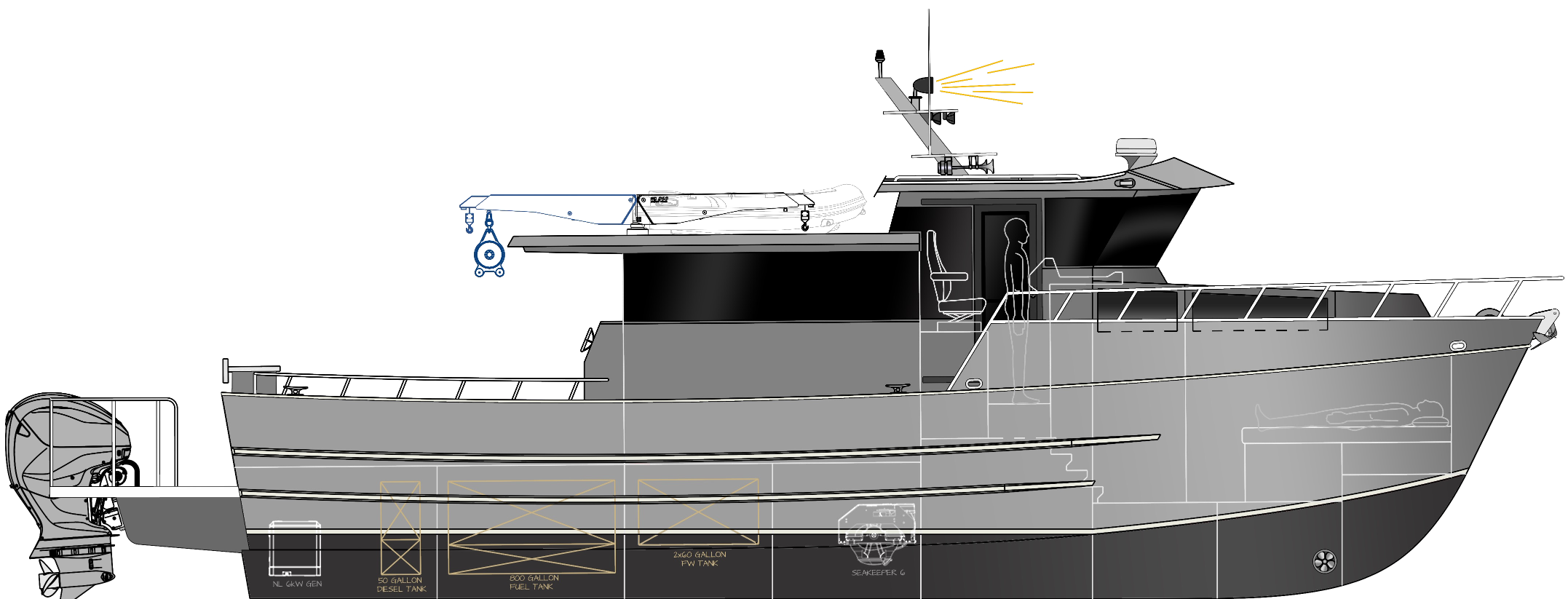
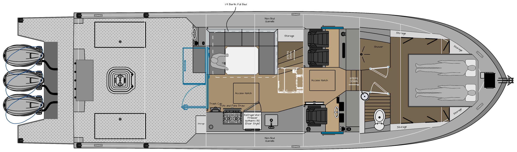
42ft Recreational Boat
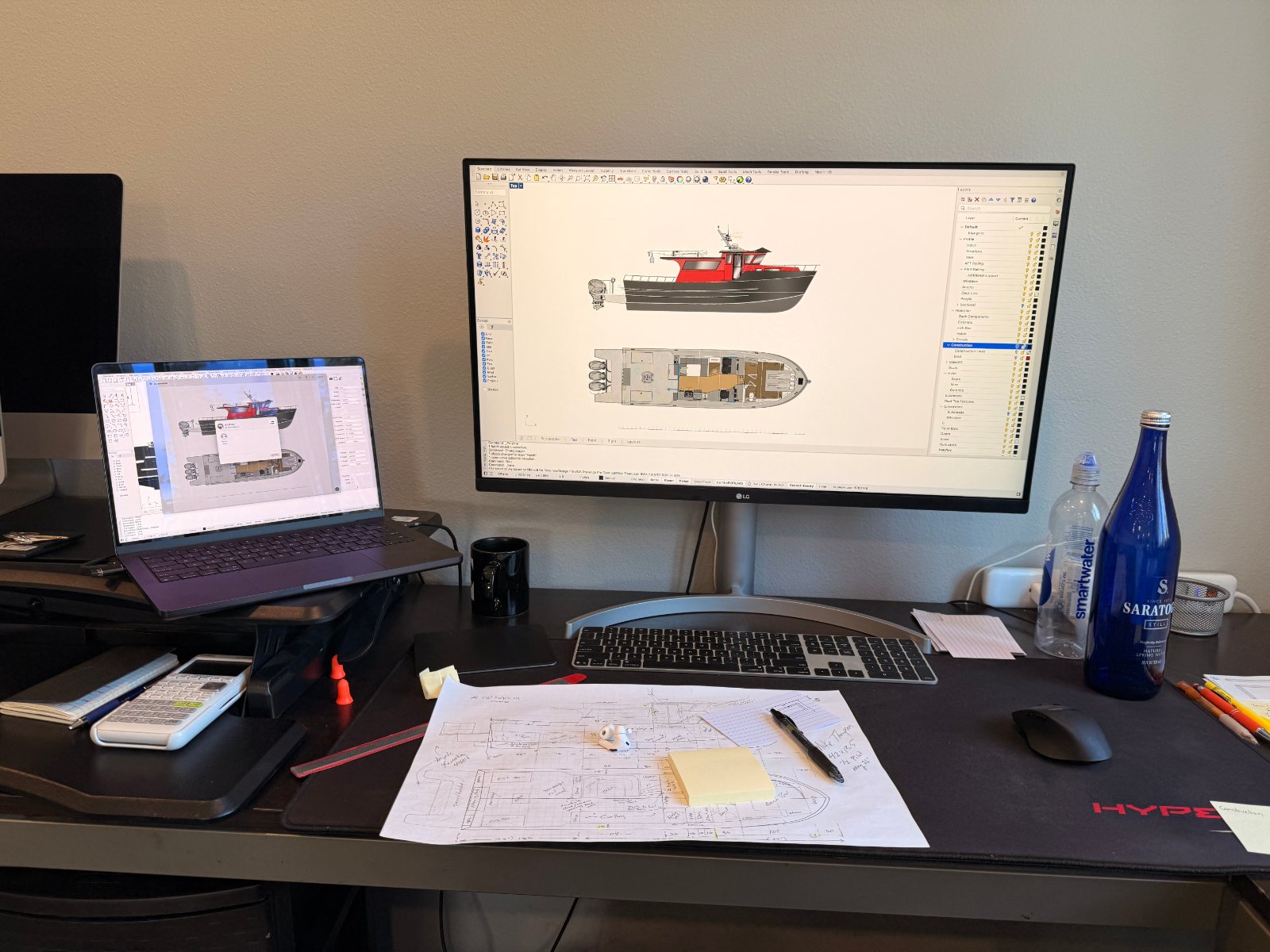
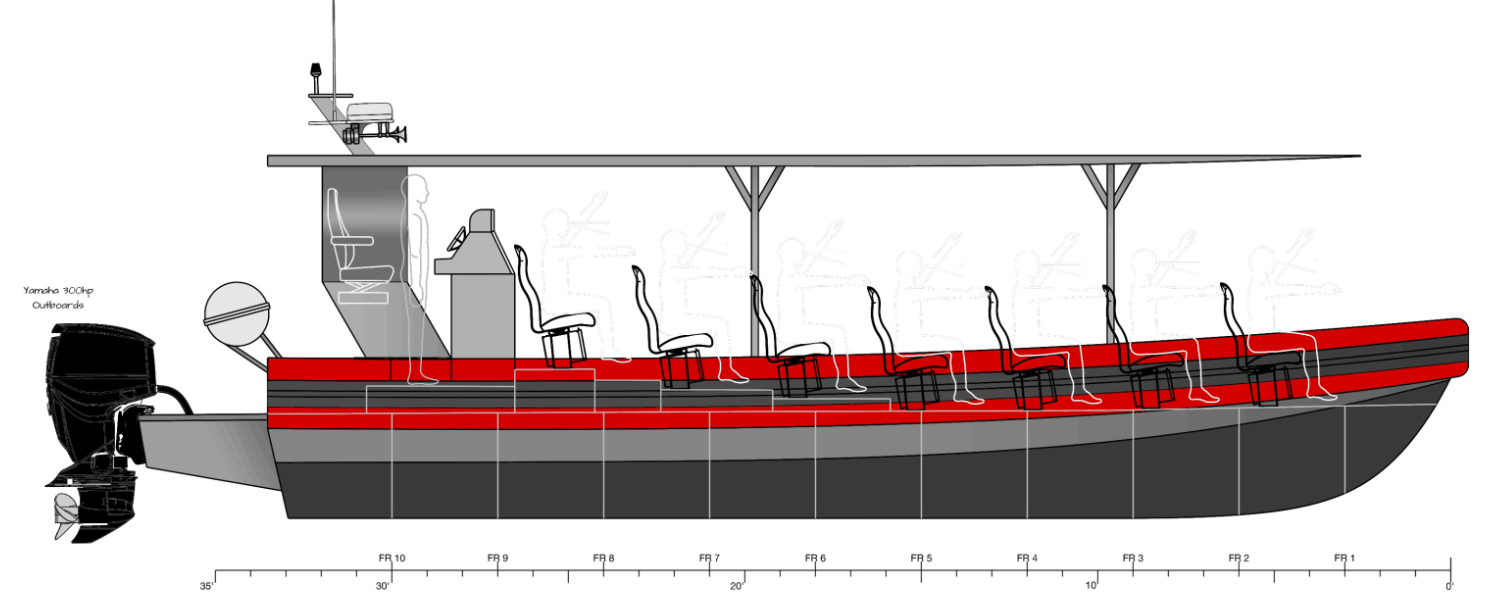
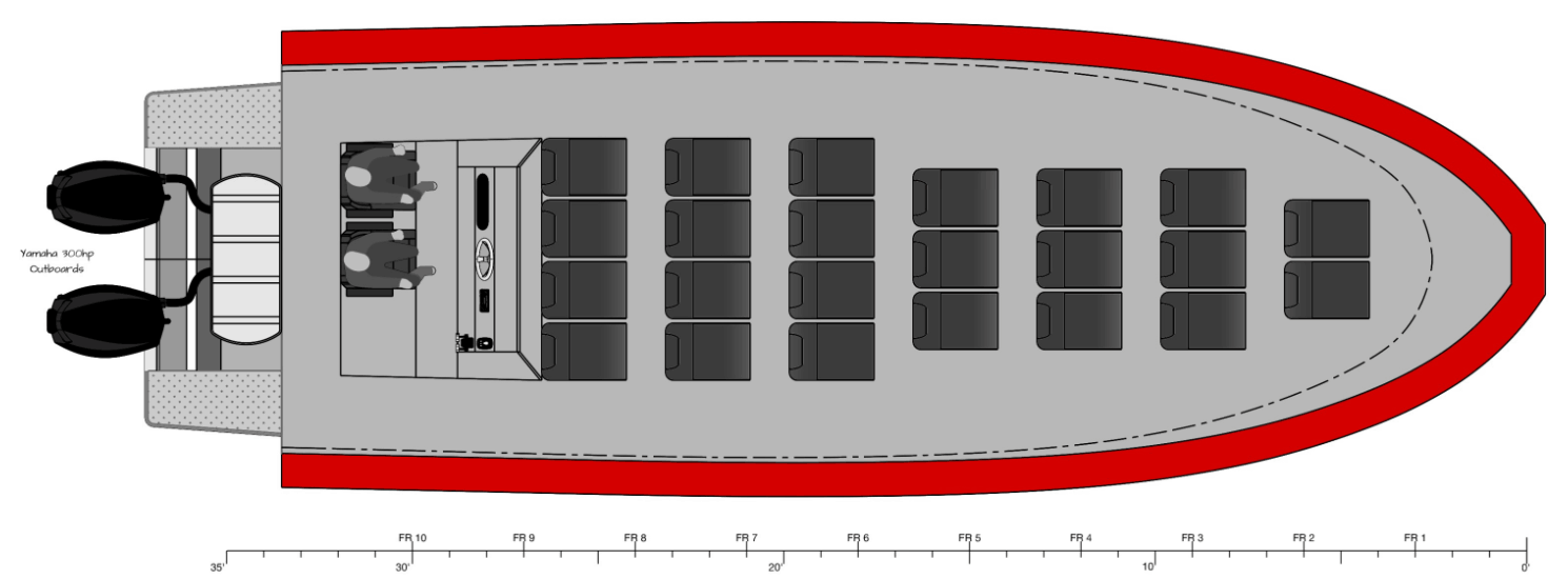
Created conceptual drawings from client specifications, this was used in the meeting that the client signed the $1.9 million build contract.
From Concept to Stability
1. The proposal
Every summer 1.5 million tourists arrive in Juneau by cruise ship looking for an Alaskan adventure. Bay Weld has built dozens of 50–70ft passenger catamerans to take them whale watching.
Currently the whale watching experience has become so commercialised with larger boats taking 100-200 people out at a time that the experience of hearing the whales and feeling connected to them has become harder to find. Thus, Bay Weld looked to fill a market gap for those tourists who want to feel like they are actively searching for whales. The solution was a boat that provides the experience of being on the water line, giving the viewers the ability to watch as whales breach.
Two requirements framed the initial design process: One standard 25-person life raft on board, and a roof spanning the full length of the vessel — Southeast Alaska's rain doesn't wait for whale watchers.
To start designing I started with a vision for how the customers should feel: close to the water, close to the whales, and small enough to feel like a private trip.
2. Turning an existing hull into a RIB
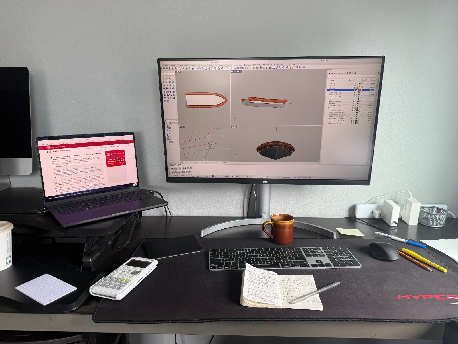
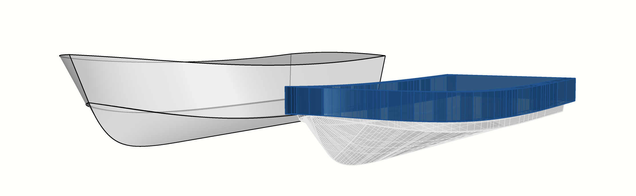
The original 35' x 12' hull had sea trial results that worked , so it carried its stability entirely in freeboard. A collar changes the arithmetics of the hull: it does its work at around 5 degrees of heel, which is exactly where a boat full of passengers leaning over one rail needs it. Once the collar was doing its job, the freeboard and the deck could both come down.
Dropping the deck lowers the vertical centre of gravity, and a lower VCG buys back righting arm across the whole range — so the boat gets easier to board, easier to work from, and stiffer, all from the same change.
3. Estimating the weight
4. Proving stability
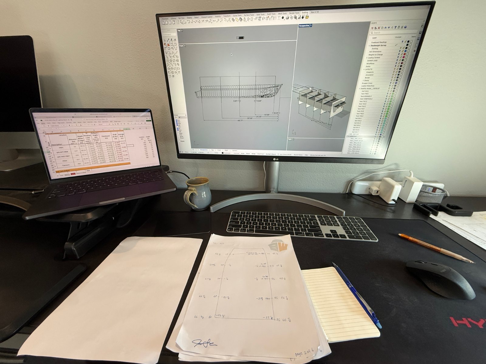
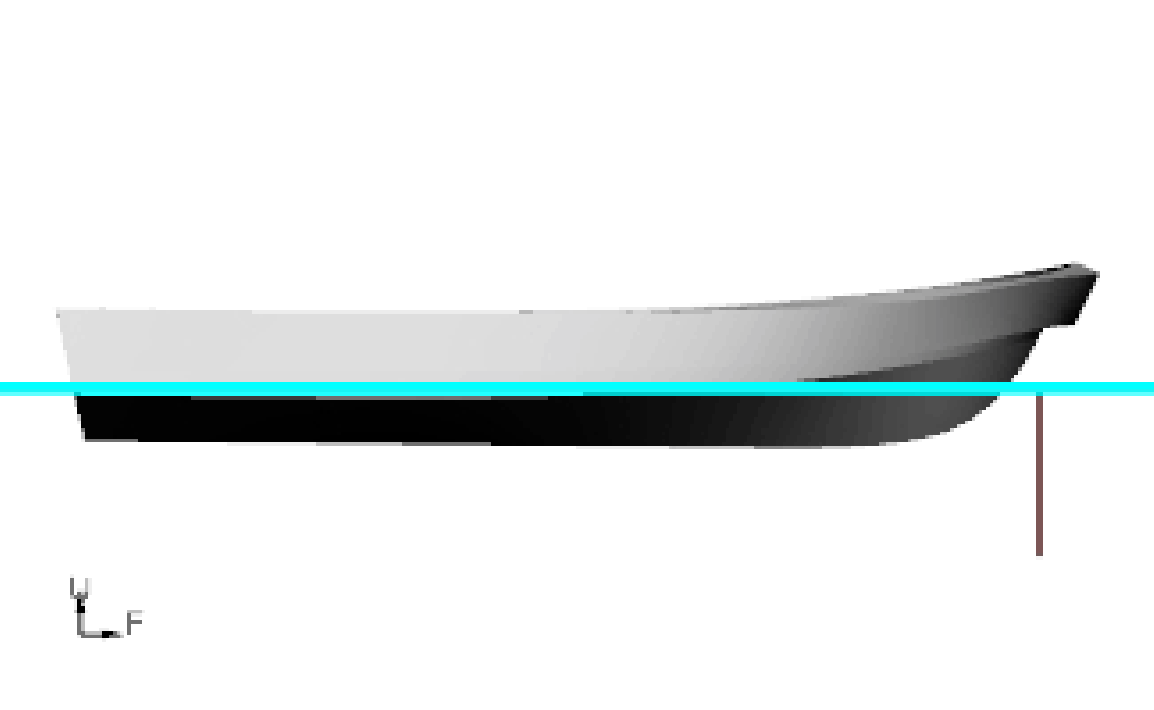
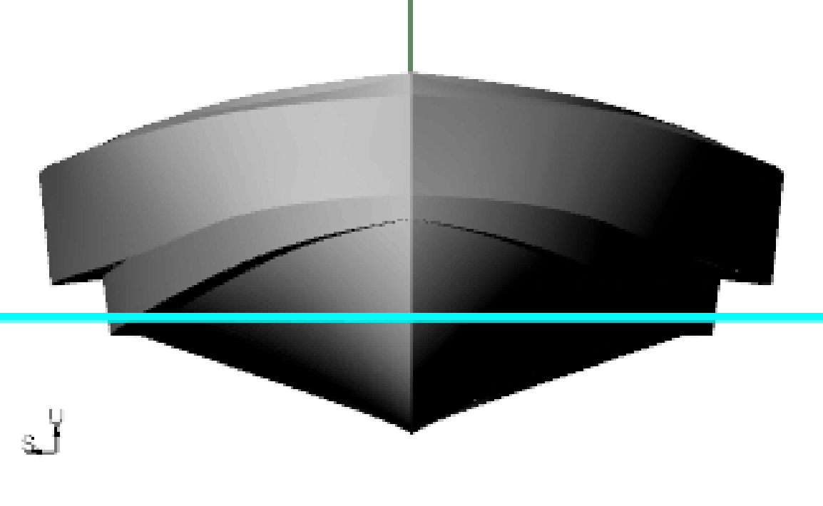
With the hull trimmed down and the collar added, we took the mesh into Orca and ran the stability calculations against 46 CFR Subchapter T. All passanger were to be modeled at the beam of the collar with no downflood points crossing below the waterline. It is a loop with regulations. Run the case, read where it was marginal, adjust the hull, run it again.
After 4 iterations we landed on a hull we were happy with: one that met the requirements with margin, kept the lowered deck, still had the signature Bay Weld look, and held at 5° heel.
5. Results
The final collared hull passed all four 46 CFR 170.173(c) criteria with passengers at the collar, each with margin.
6. The general arrangement
Getting COIS approved and boats on the water
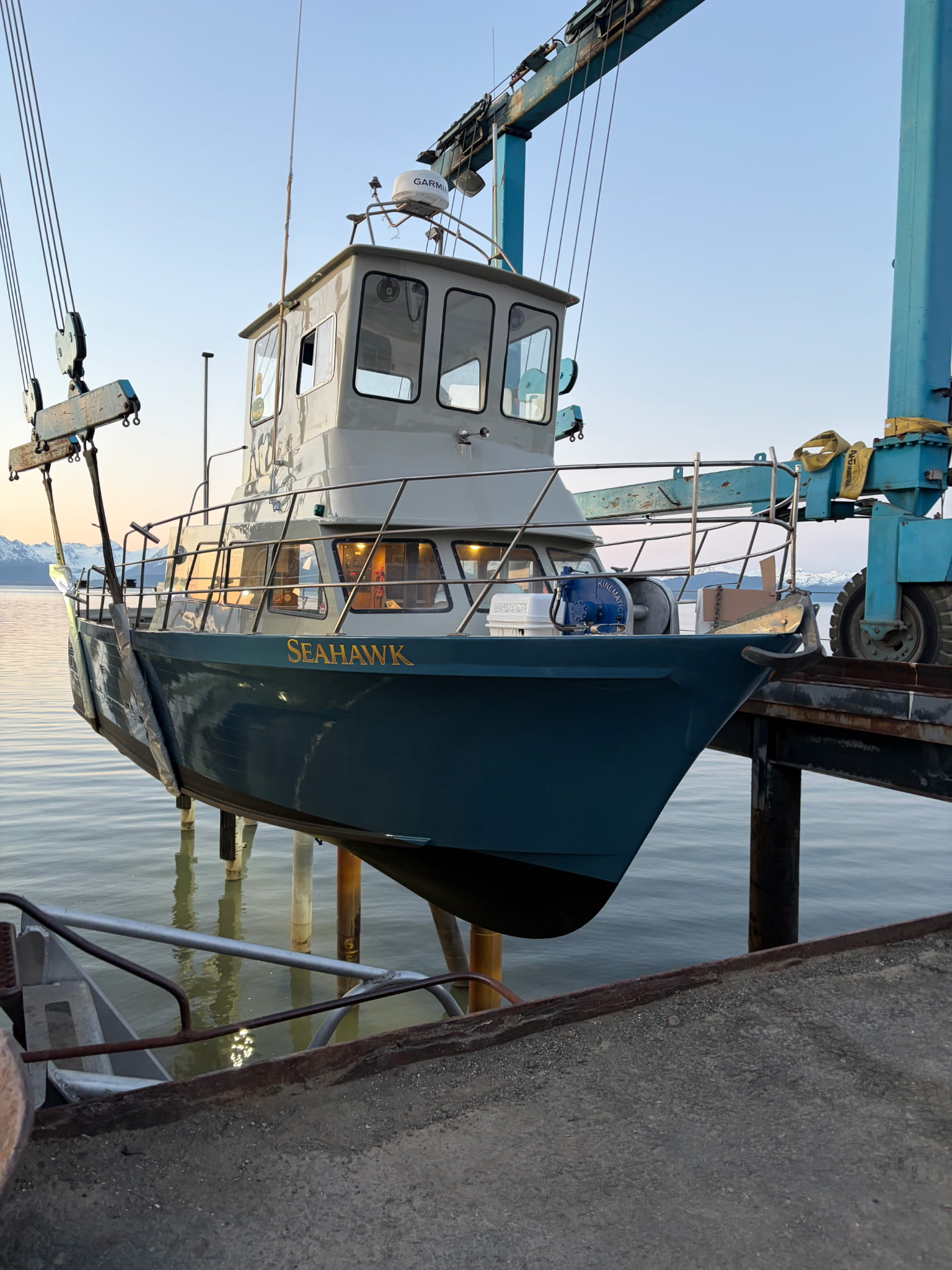
Deadweight surveys
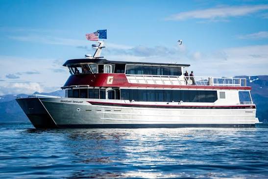
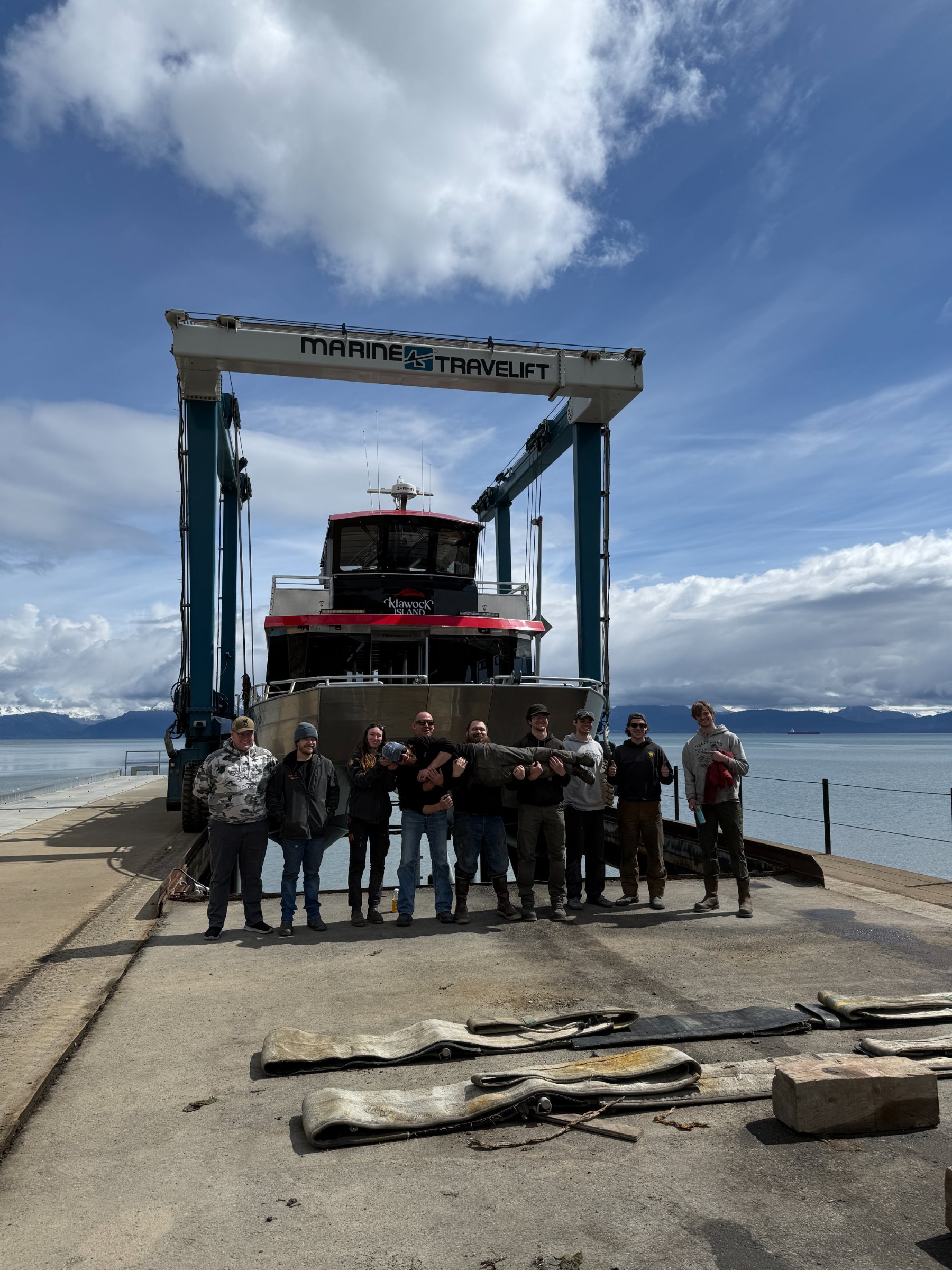
1 Incline test
Rating an A-frame for a 7-ft extension
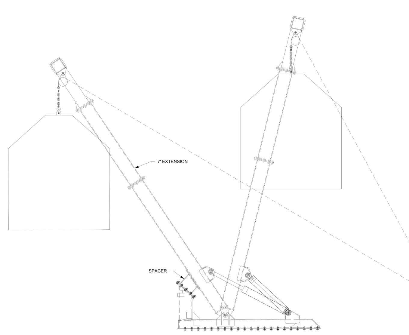
Original configuration
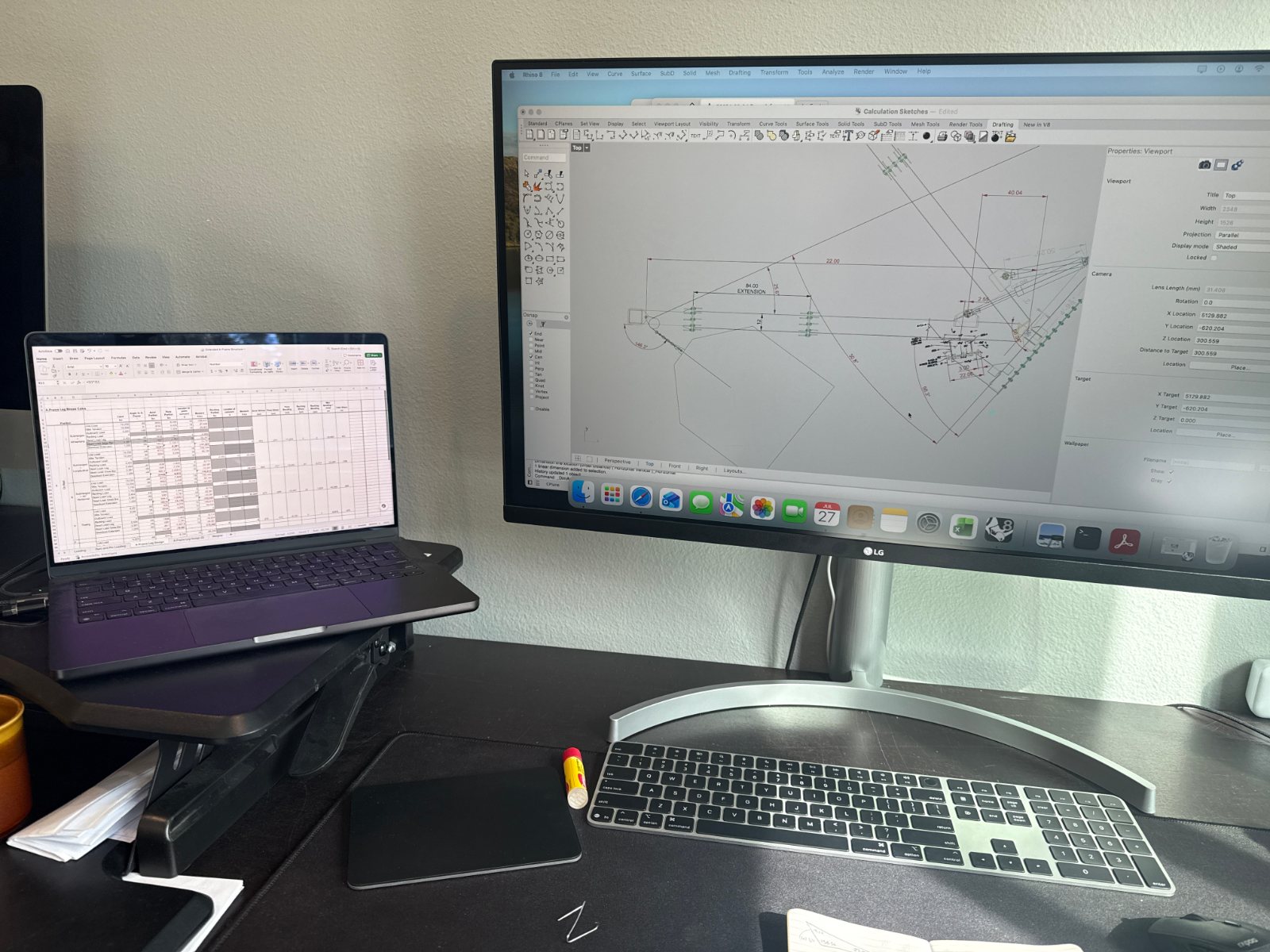
The client uses an A-frame to launch and recover a 700 lb data-collection instrument over the side of his vessel. As the instrument was raised and lowered, it kept swinging into the hull. He wanted the frame extended so the instrument would hang farther outboard. Since it weighs only 700 lb, he didn’t need the frame’s full 10,000 lb rating, which left room to give up capacity in exchange for reach.
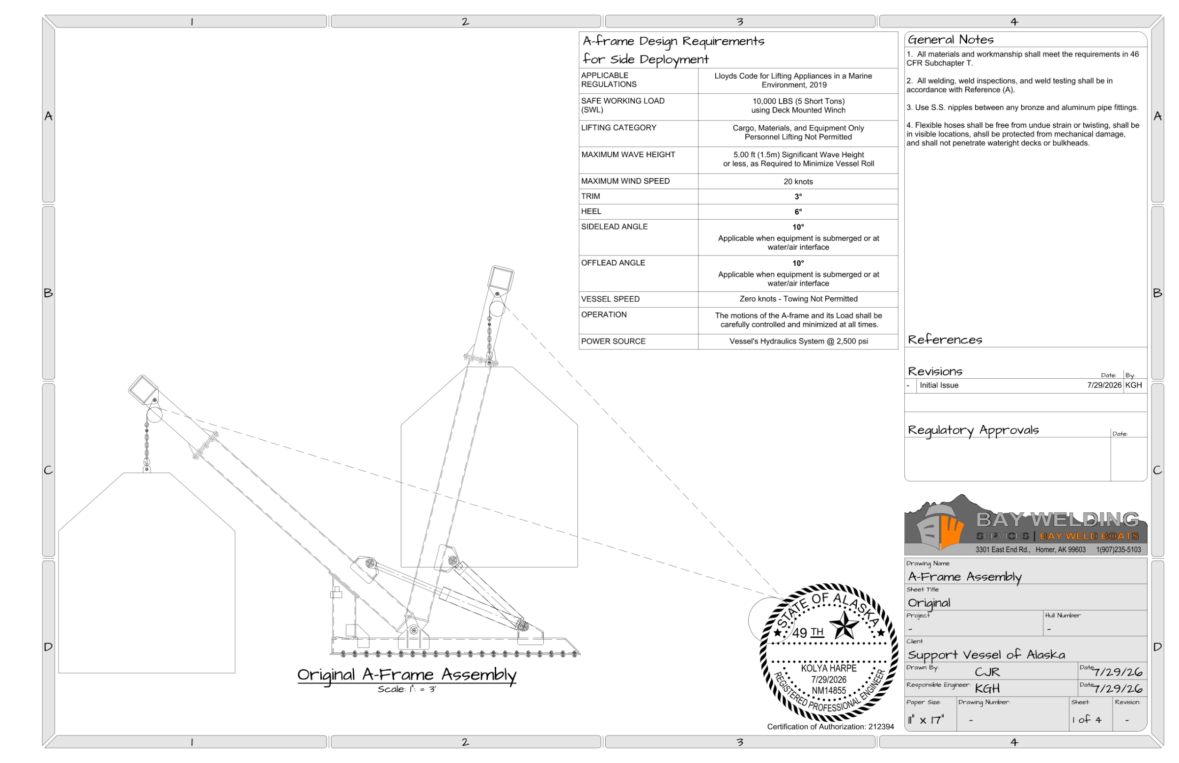
New design with extension
A 7 ft extension moves the lift point clear of the hull. The longer arm, however, increases the loads throughout the existing structure, so the original rating no longer applied and a new safe working load had to be defined. We identified five critical points in the frame and modeled each one, keeping the maximum stresses, strains, and forces at or below the values in the original design.
The rest, the cradle the A-frame sits on, turned out to be the limiting component. I took its peak load in the original design as the ceiling and solved for the working load that reaches that ceiling with the extension in place. The result is a new SWL of 5,000 lb: half the original rating, and still more than seven times the instrument’s weight.
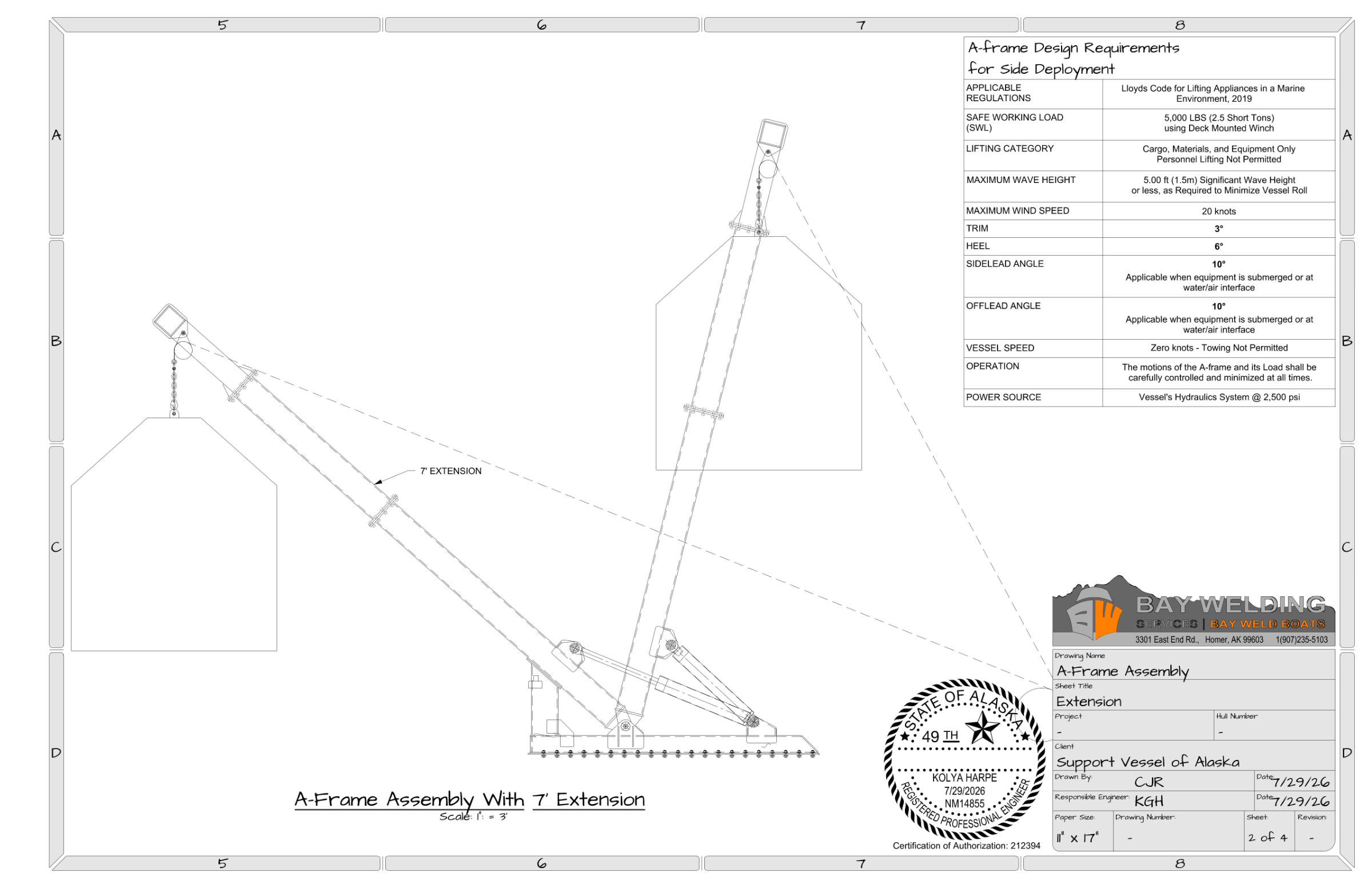
The ram set the limit
The hydraulic ram was the limiting factor, so I set its value as our max and solved for a safe working load of 5,000 lb. I then used 5,000 lb to analyse the other four points on the frame. Tap a point to see how it compares with the original.
As-Built Electrical Drawings
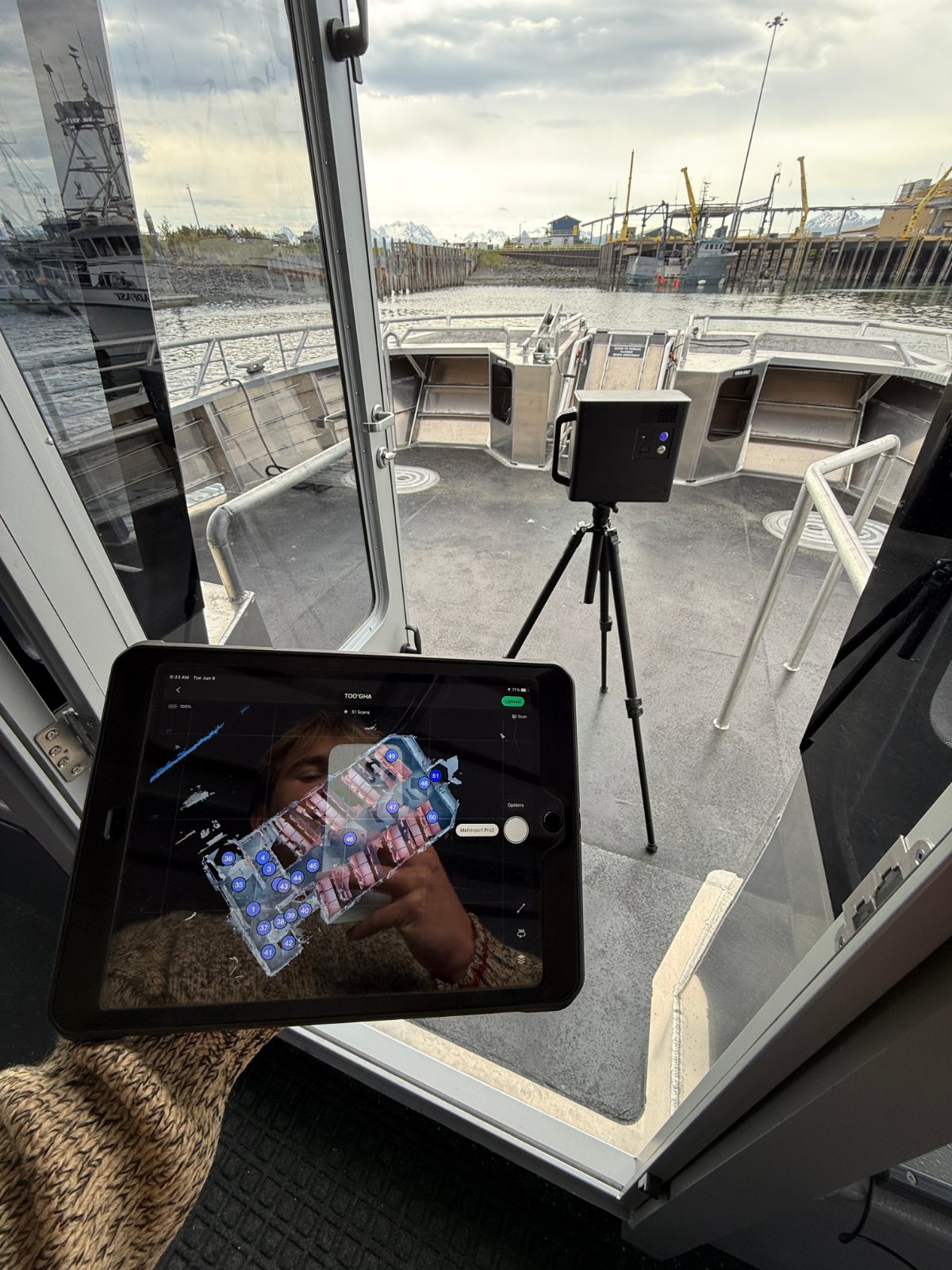
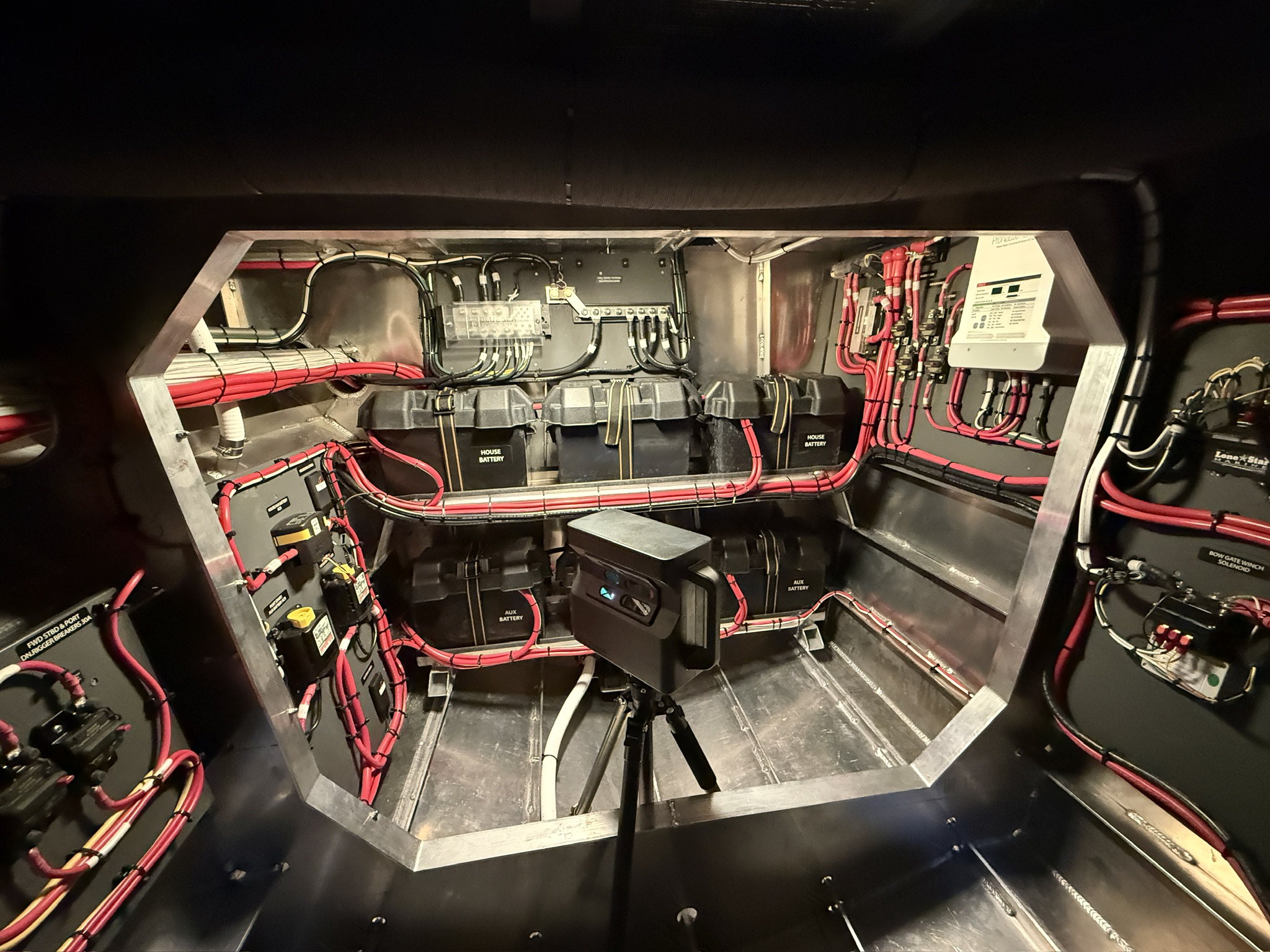
Matterport scan
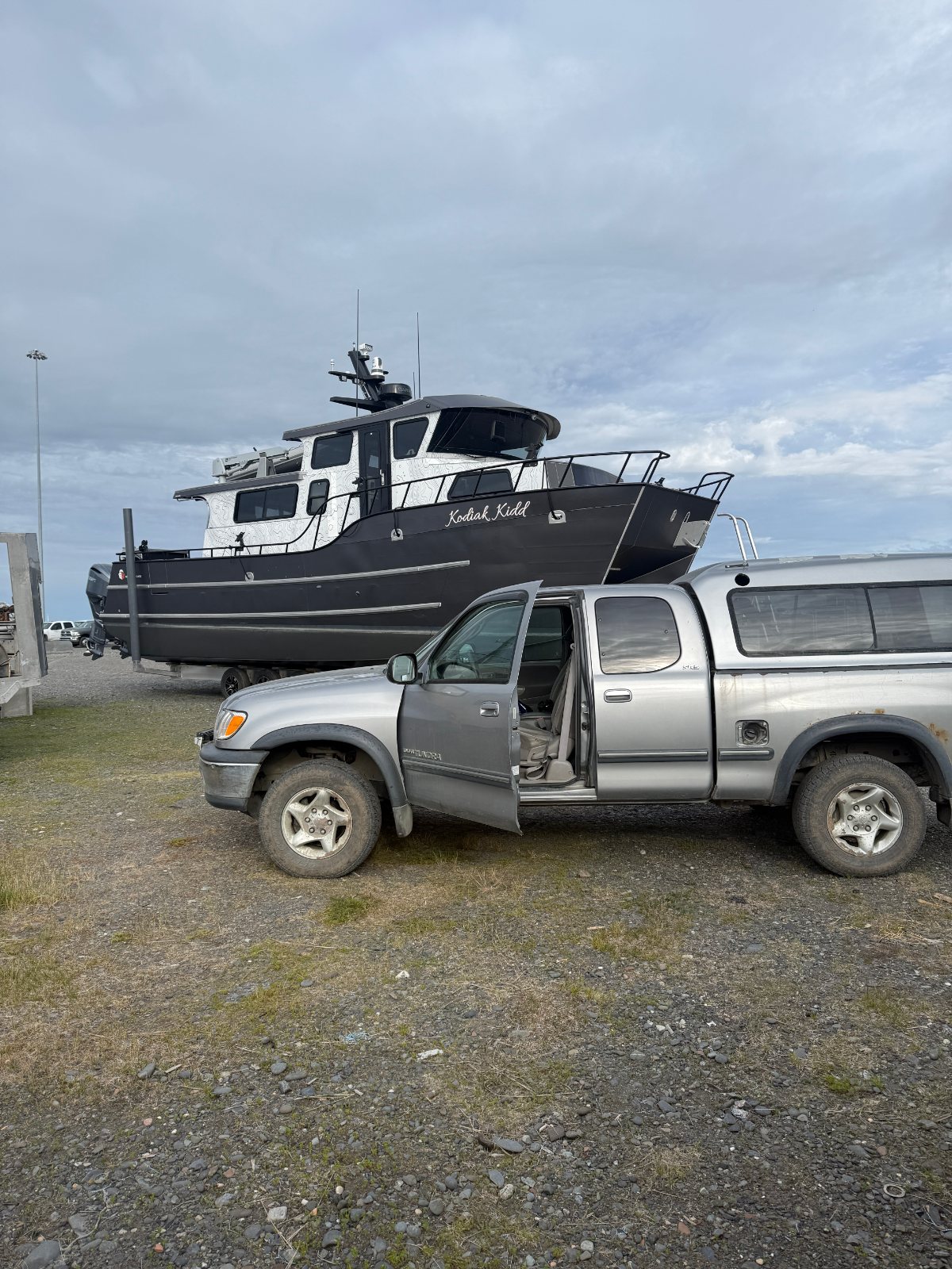
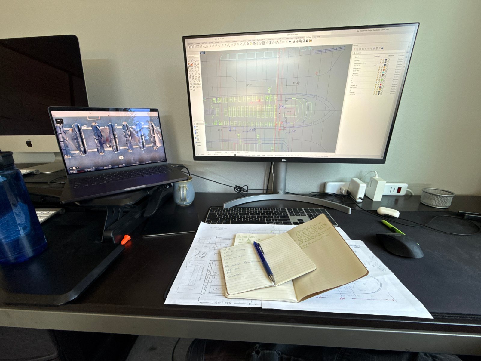
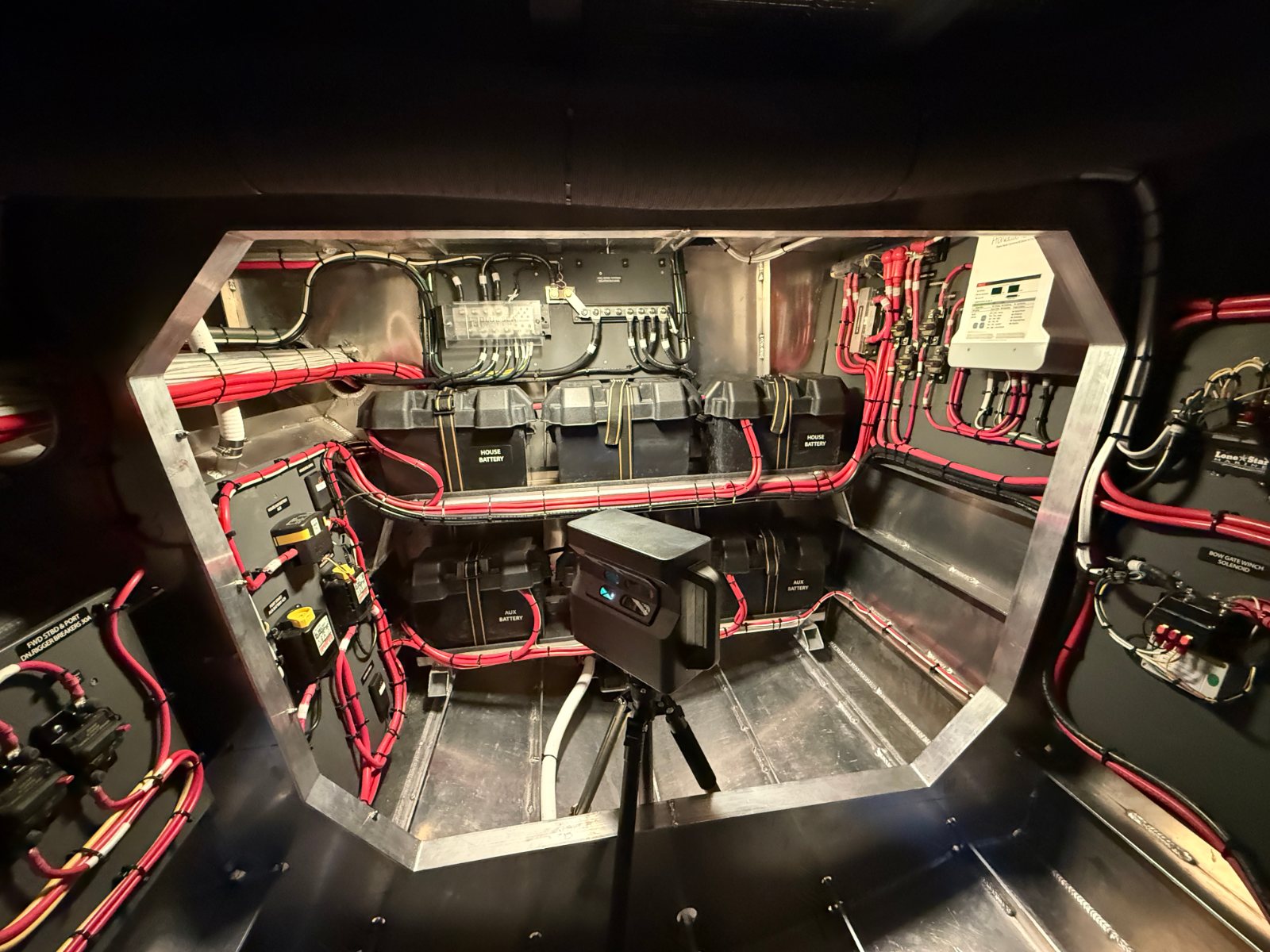
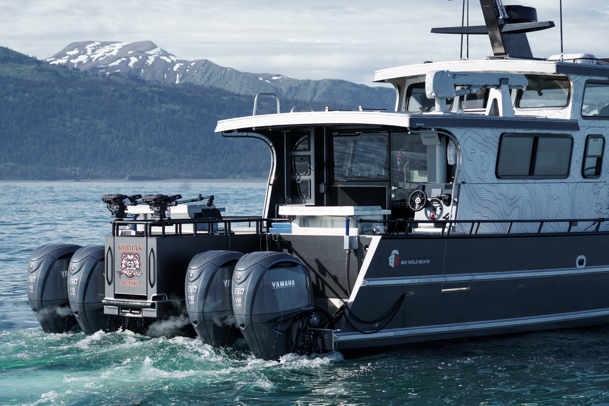
For Kodiak Kid I followed the same four steps: gathered the electricians’ hand drawings, traced and verified the runs on the boat, filled the gaps with the electricians, then drew the as-built schematic in Rhino.
The lower photo is inside Kodiak Kid: It shows the MatterPort scanner, I would place it throughout the boat to create a 3D map for future troubleshooting.
My Two Weeks on the Shop Floor
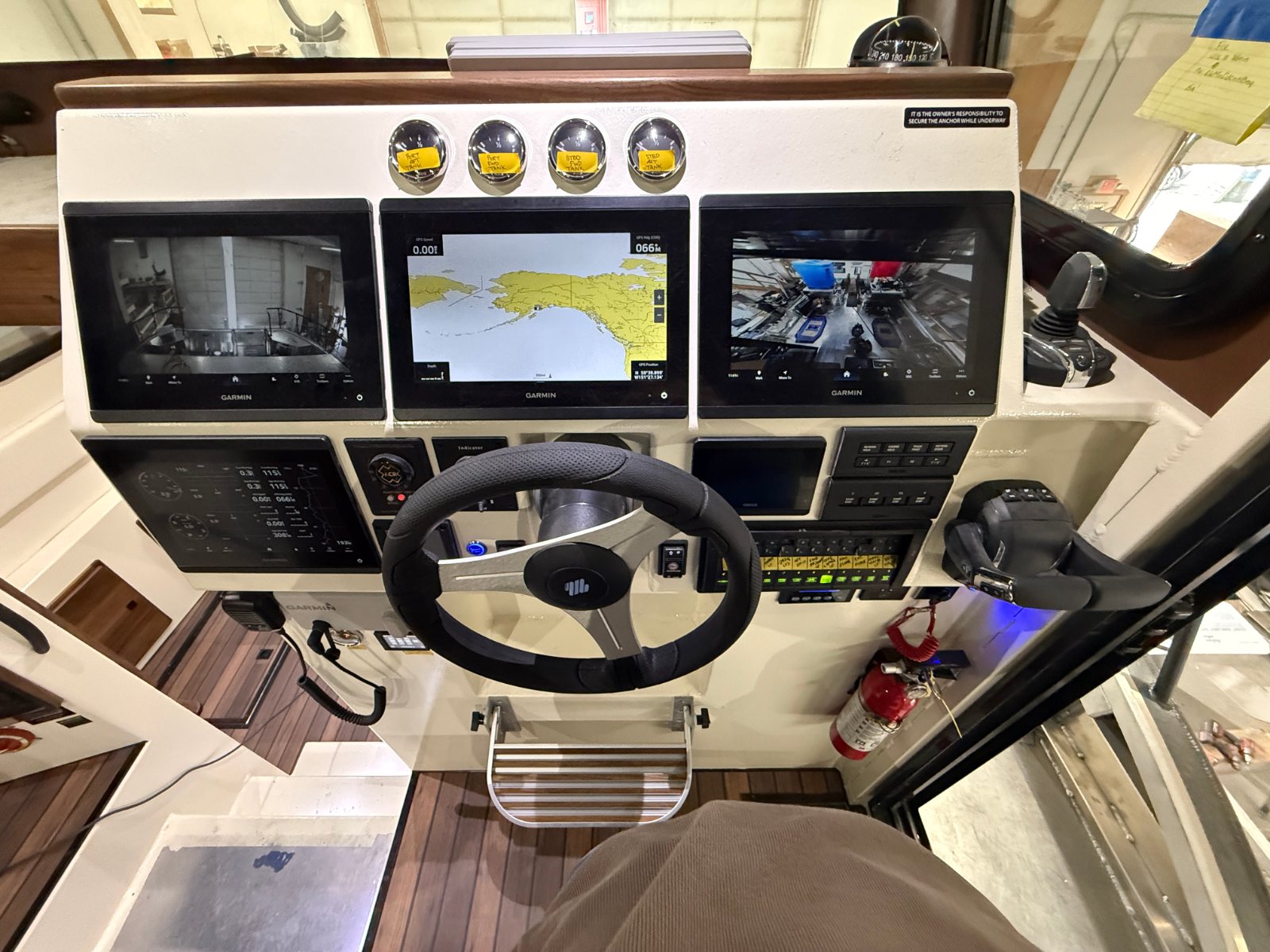
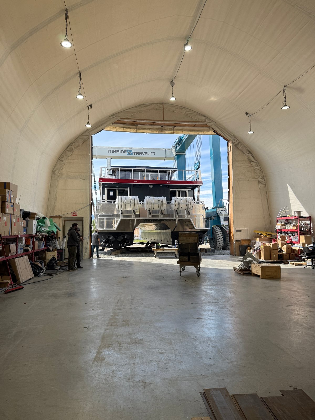
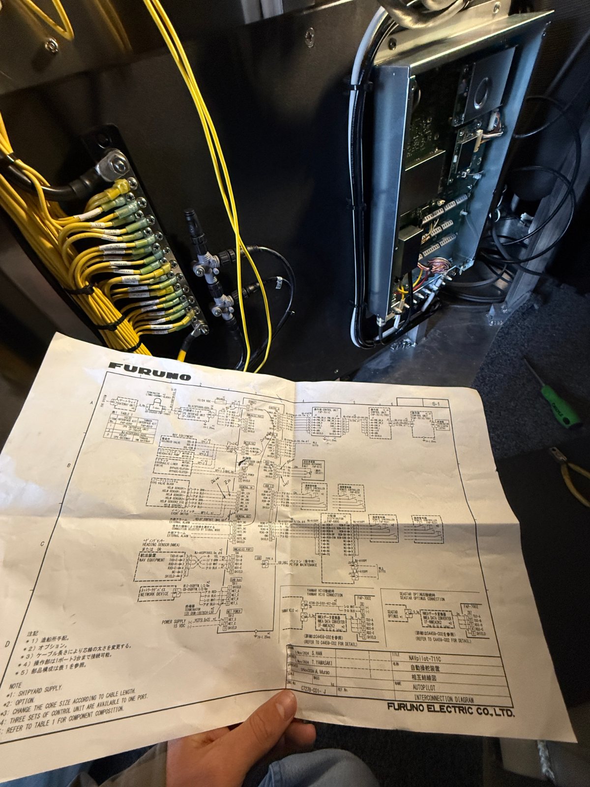
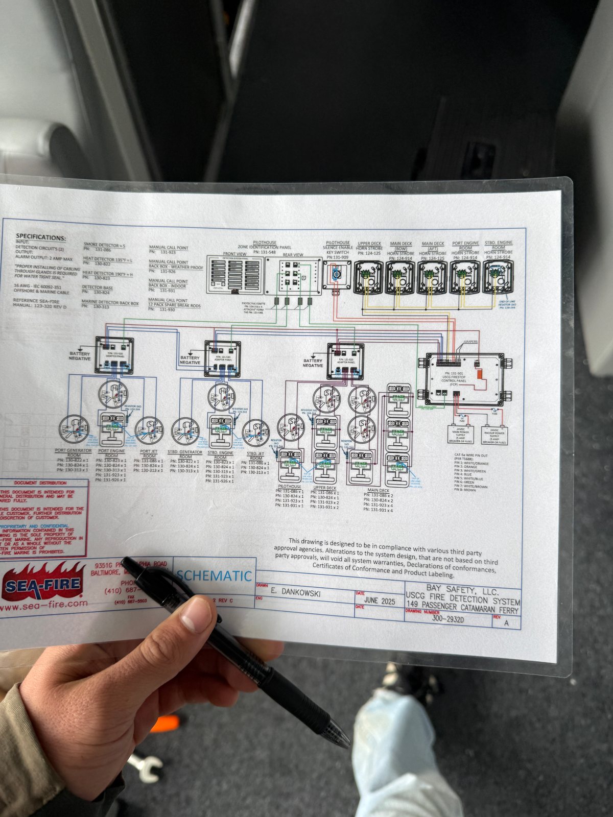
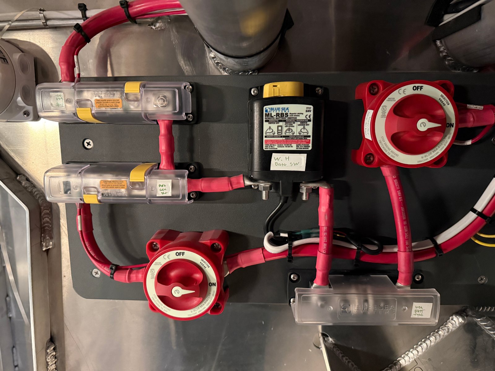
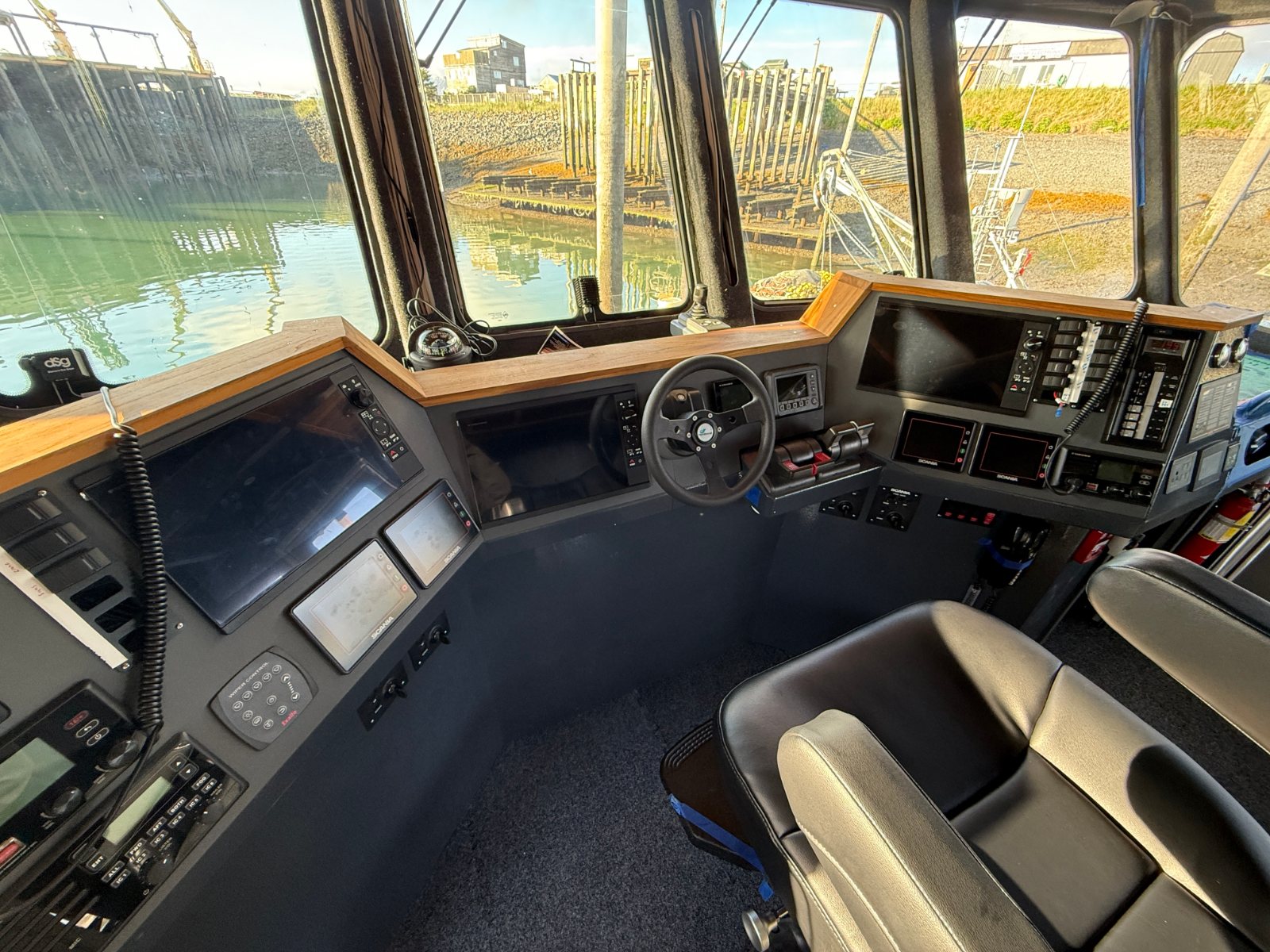
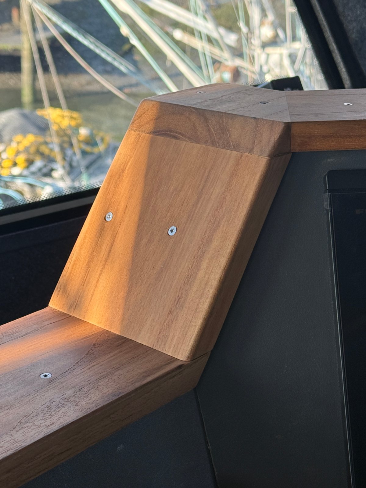
Worked 2 weeks on the shop floor finishing a vessel: tested and integrated onboard electrical systems, set up AIS, built helm finishes, ran Matterport scans, and interpreted drawings and manuals for the build crew, bringing fabrication lessons back into design work.